|
Illustrated Tour of the Installation Process |
|
Steps to upgrade the Performas 5xx to the MicroMac PowerPC 5200 |
|
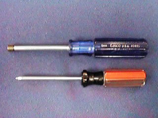
Tools You Need: |
|
|
Philips screw driver |
|
|
5 mm or 3/16" socket drive |
|
Step 1: |
Verify the proper operation of your Performa 5xx |
|
verify the current system software that it is compatible
with the MicroMac PowerPC 5200 upgrade. |
|
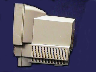
Step 2: |
Prepare your computer |
|
Shut down your Mac properly. |
|
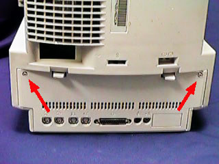
Step 3: |
Open your Mac |
|
Remove the two screws on each side of the back panel. |
|
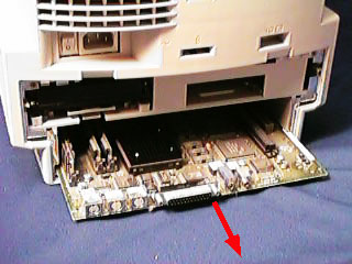
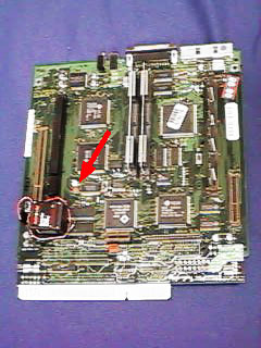
Step 4: |
Remove the logic board |
|
Pull the logic board out of the chassis. |
|
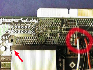
Step 5: |
Preparing new logic board |
||||||||
|
verify the connection of the battery on the new logic
board.
|

|
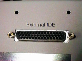
Step 6: |
Preparing for optional Ext. IDE connection |
|
connect the IDE cables if you purchased the ext IDE
option. |
|
Step 7: |
Installing the 5200 logic board |
|
Have the Performa face down and slide the new logic board
into the chassis. Watch for the two rail slides which guide
the logic board as well the metal standoffs on the bottom of
the new logic board so they do not get caught while sliding
it in the chassis. |
|
Step 7a: |
Test the new logic board |
|
Before you continue, you may connect the main power cord
and the keyboard and "fire up" the new logic board. |
|
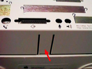
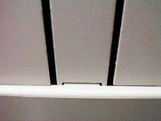
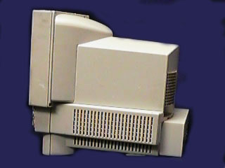
Step 8: |
Install the extension chassis |
|
When installing the extension chassis there are 3 points of support. The two screws on the top and the tap on the bottom side center. Make sure the opening snaps into the center tap of the main chassis. You need to press onto the metal tap in order to clear the plastic tap. |
|
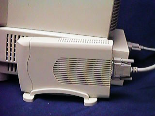
Step 9: |
Secure the extension chassis |
|
Use the provided screws (M3x8) to secure the extension chassis. |
|
Step 10: |
Connect the external IDE drive |
|
If you have purchased the external IDE option, you may connect it now or after you have verified the proper operation of the new system. |
|
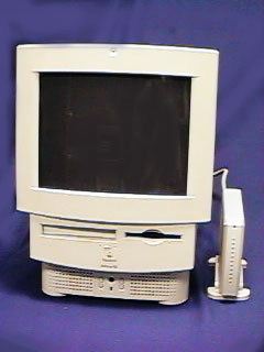
Step 11: |
Enjoy your increased speed |
|
Home | What's New | Company Profile | Products | MacSpecs | Software | Sales | Tech Support | Online Resources |
|
|
|
|
|
MicroMac Technology, 27121 Aliso Creek Rd, # 125, Aliso Viejo, CA 92656, USA, Tel: (949) 362-1000 Fax: (949) 362-5428 |
|
|
Copyright ©1996, 97, 98 MicroMac Technology |
This page was last modified on July 30, 1998 |